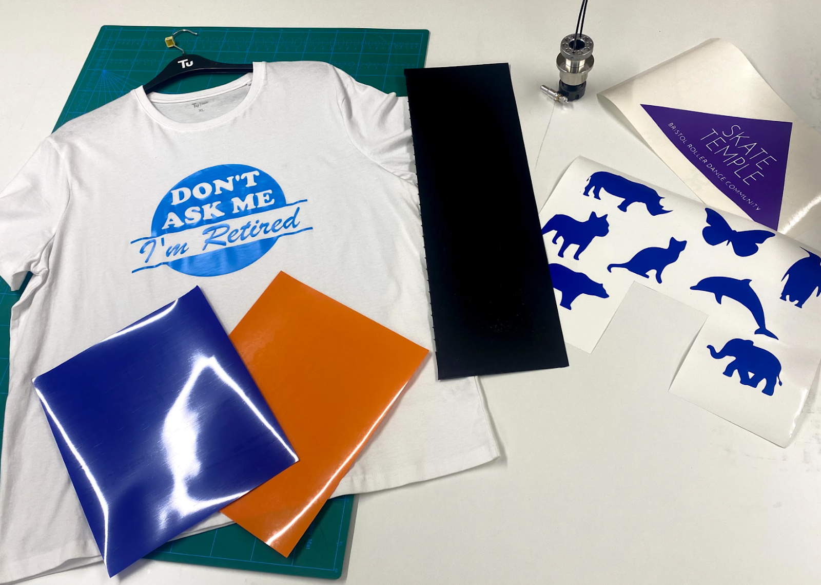
What we will make
Our project is to make some animal stickers.
Process overview
Here’s a flow chart to illustrate the processes involved, followed by links to each article in this tutorial.

What are the different types of vinyl?
There are 3 main different types of vinyl, used for different purposes:
Self-adhesive vinyl
Heat-transfer vinyl
Rigid vinyl
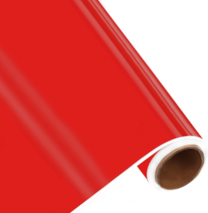
Self-adhesive vinyl
Self-adhesive vinyl comes in many different types which vary in thickness, colour and finish. Adhesive vinyl is cut with the vinyl facing up and the paper carrier sheet down.
This can be used for signage and branding in both indoor and outdoor environments.
Heat transfer vinyl
Heat transfer vinyl (commonly called HTV) is not sticky and instead is fused with heat to fabrics, such as shirts, tote bags, coats, scarves, blankets, stuffed animals, etc. It is designed to be applied with a heat press or an iron. HTV is cut with the clear shiny side facing DOWN and the duller back of the vinyl facing up.

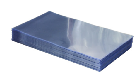
Rigid vinyl
Rigid vinyl can come in a range of thicknesses from 70- 500 microns. Most commonly made from PVC, this clear vinyl has a range of applications.
What Vinyl can I use?
CNC Stylus has been designed to be used with thinner vinyl such as self-adhesive and HTV. You can potentially cut thicker vinyl but this needs to be taken with a slightly different approach.
Where can I buy vinyl from?
You can buy vinyl with a wide range of colours and types from most online stores, for example this site.
What are the different blade types?
There are 3 different types of blade, defined by their cutting angle. The different angles can be applied to different material types and thicknesses. The diagram below represents how the different angles are measured.
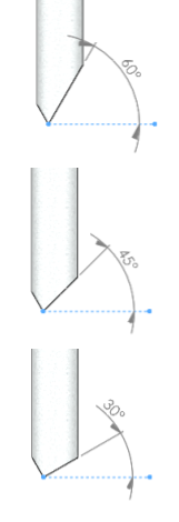
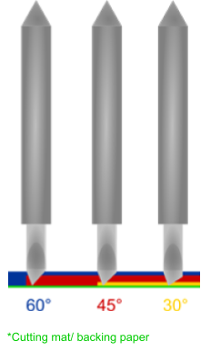
Note that the steeper the angle, the deeper the blade extends.
How to identify which is which
Blades ship with a protective cap, and the colour helps indicate the blade’s angle. Watch out though, it’s easy to put the wrong cap on a blade!

Angle (degrees) | Colour cap |
60 | Blue |
45 | Red |
30 | Yellow |
What are the different blades types used for?
Different blade angles work better for different materials.
Theory
A steeper angle (e.g. 60°) can reach deeper, and is therefore used for thicker materials. But, this attracts a higher cutting load (which may cause tearing).
A shallower angle (e.g. 30°) has a reduced cutting load. But it cannot reach as far, and therefore is ideal for thinner materials.
A good rule of thumb is to use as shallow an angle as the material thickness will allow.
Examples of use
Angle (degrees) | Colour cap | Material used |
60 | Blue | Thick media such as card, rigid vinyl, fabric, cork, and magnet |
45 | Red | Medium media such as vinyl (adhesive and heat transfer), paper and thin card |
30 | Yellow | Thin media such as film or window tint |
The cutting blade is held in place with a magnet which sits on a bearing. This allows the blade to easily swivel and rotate.
To remove the blade, simply press on the ejection pin as shown below.
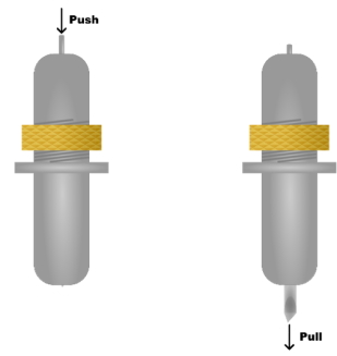

You can then remove the blade by pulling it out. Remember to replace the protective cap to ensure your blade does not get damaged or blunted.
How do I generate the files for SmartBench to draw?
A CAD/CAM package is needed to design the drawing. This package will then export the toolpaths for SmartBench to draw with CNC Stylus.
What CAD/CAM software will this tutorial use?
In this tutorial will design our drawing in Vectric.
Vectric works by:
Defining a general job setup
Importing an SVG
Creating a drag knife toolpath
Exporting the toolpath to a file
Can I use other CAD/CAM packages?
You are welcome to use other CAD/CAM packages to generate the files for drawing. You can use a number of different CAM software packages. Click here to learn more about other CAD/CAM packages which are compatible with SmartBench.
Can I skip this, and just download the files?
Yes! You can download the file made for this tutorial here:
- Vectric project file for vinyl cutting animal stickers (this file is NOT for export to SmartBench. It is to be opened in Vectric. It can then be used to generate job files).
- Job file for vinyl cutting animal stickers (this is the file which was exported and sent to SmartBench).
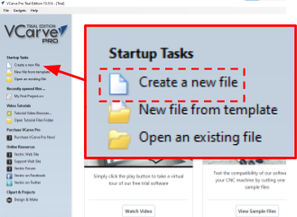
Create a new job file
Start by creating a new file by clicking on Create a new file link.
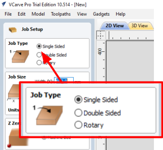
Job type
Select Single Sided, we will only be cutting on one side.
Job size
Specify the minimum dimensions of the stock material you will be using.

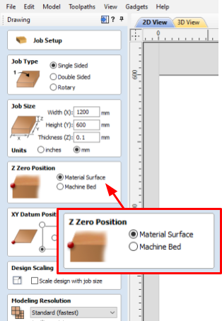
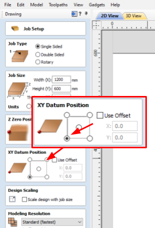
Z datum position
We will use “Material Surface” as Z datum for the job. This means we will be registering the initial position of the tool on the top surface of the material, rather than the surface of the spoil board (for more theory about datums click here).
XY datum position
Select the bottom left corner of the bounding box (for more theory about datums click here).
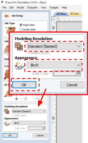
Modelling resolution and appearance
These settings do not affect the cut path and are used only for preview rendering. Select Standard (fastest) from the drop down to speed up the preview rendering of the cut path. Select Birch in Appearance drop down.
Import SVG
For this example, we are going to import an SVG file, which has the animal shapes already drawn.
You can download the SVG which we used by clicking on this link.
An SVG is a type of image file which uses vectors instead of pixels, to define shapes. This means toolpaths can be assigned to the shapes. |

First, we will import the SVG by press Import Vectors
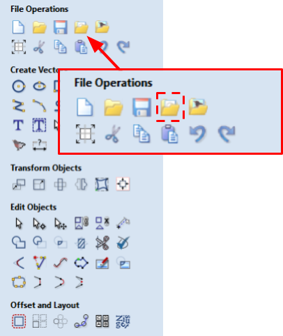
We can then select our SVG to import and press Open

Our SVG will now appear in our window
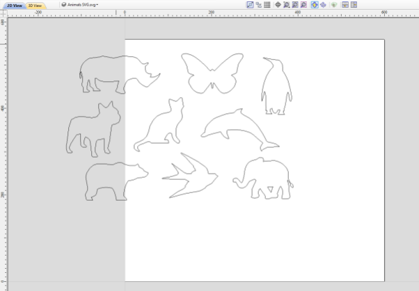
We can now center our SVG to the job.
In this case, we need to group our animals into one object.
Select the objects and then right click > Group Objects

Click on the image, the colour of outlines will change to magenta. Go to Edit > Align Selected Objects > Center In Material

We now need to ungroup the objects back into their individual vectors. Select the objects and then right click > Ungroup Objects > Ungroup back to original layers

When we create a drag knife toolpath using the gadget in the next step, we can use a dummy tool.
This means we do not need to add a new tool to the database.
We will select any tool (in this case end Mill 0.1mm)
The gadget will automatically calculate the path from the center of the tool, which means we do not need to worry about diameter. |

Drag knife gadget
Vectric VCarvePro comes with a pre-installed drag knife gadget that will enable you to create paths for cutting vinyl. A drag knife toolpath is needed as we need to accommodate for blade offset, explained below.
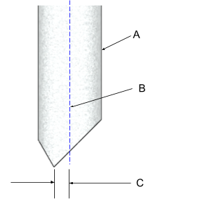
Blade Offset
The tip of a drag knife is offset by a small amount from the pivot center of the tool. This allows it to swivel as it cuts. This offset value specifies the distance between the central axis (B) and the tip (C).
NOTE: The offset we will use is 0.2mm
A: Vinyl cutting blade
B: Central axis
C: Tip offset
Creating the toolpath
Click on every shape while holding the Shift key on the keyboard to select all of them. Selected objects outlines will change to dotted magenta lines.
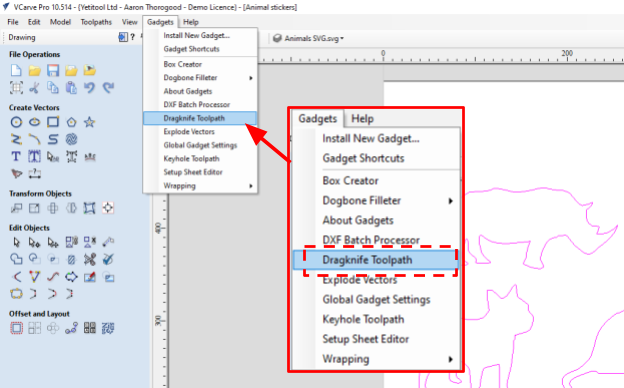
Then click Gadgets > Drag Knife Toolpath
The Dragknife Toolpath window will open
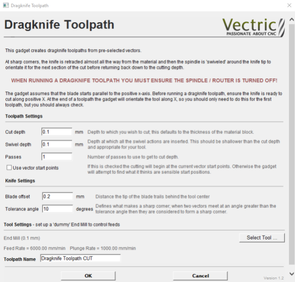
We now need to define the parameters for the toolpath as below:
Cut depth: 0.1mm
Swivel depth: 0.05mm
Passes: 1
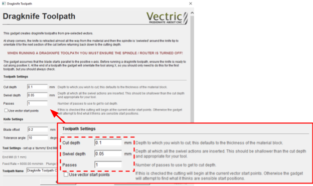
We now need to define the knife Settings:
Blade offset: 0.2mm *
Tolerance angle: 10 degrees

For the tool, we can select ANY tool available as this will act as a dummy to control feeds.
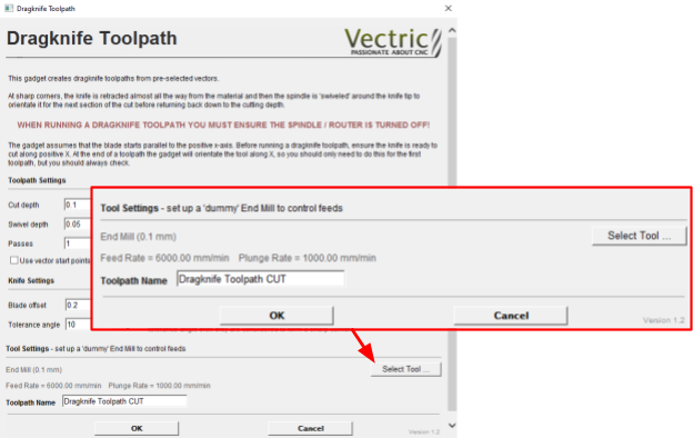
We can now press OK and the toolpath will be created.

You can view the toolpath in the 2D View tab

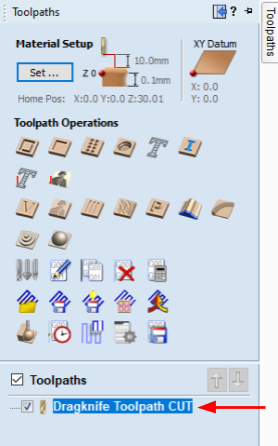
Once you create toolpaths, you can export them into a job file. You can also have a file with toolpaths already created. Click on Toolpath on the right hand side of the Vectric screen.
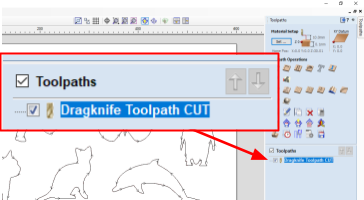
You will see a list of created toolpaths.
If the check box next to a toolpath is ticked Vectric will show a preview of this toolpath. Tick on the check box next to Toolpath to select/deselect all the toolpaths.
In this example we will only export a single toolpath into a job file.
Select the toolpath name, this will highlight in blue
Select the save toolpath button. The toolpath selected and the tool used will be displayed under Toolpaths to be saved

Select Yeti Tool SmartBench in the Post Processor drop down.

Click on Save Toolpath(s)

Select the location for the job file and its name. By default Vectric will name the file after the toolpath’s name.
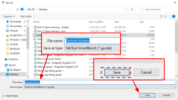
We will name this Animal stickers
Your job file is now ready to be transferred to SmartBench.
How do I transfer files to SmartBench?
You can either transfer files to SmartBench via Wi-Fi or using a USB stick.
Please click this link to find out how to do this.
How do I choose the correct spoil board?
When selecting a suitable spoil board, we need to ensure to use something
Rigid
Flat
We would recommend using a 12mm melamine faced MDF board.
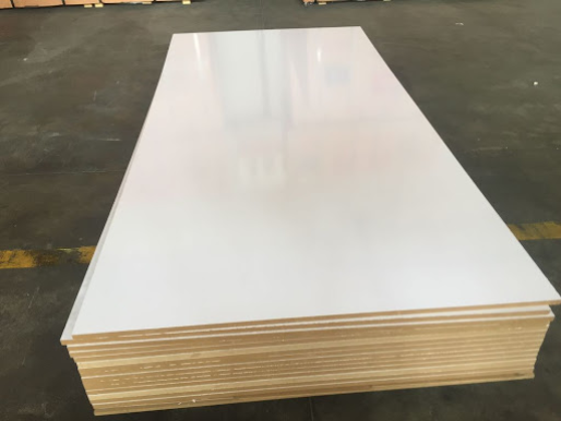
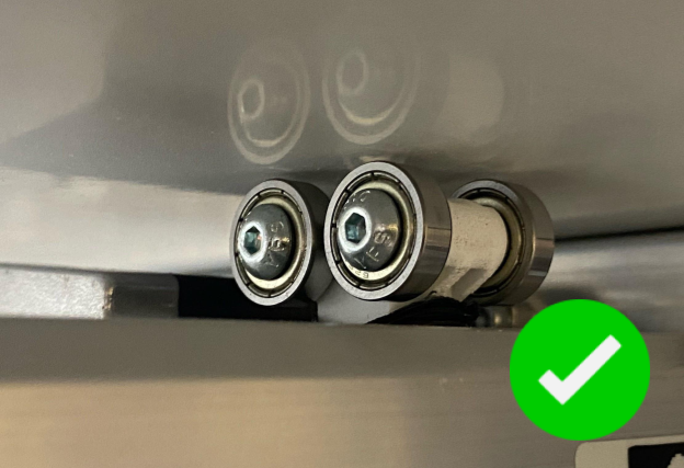
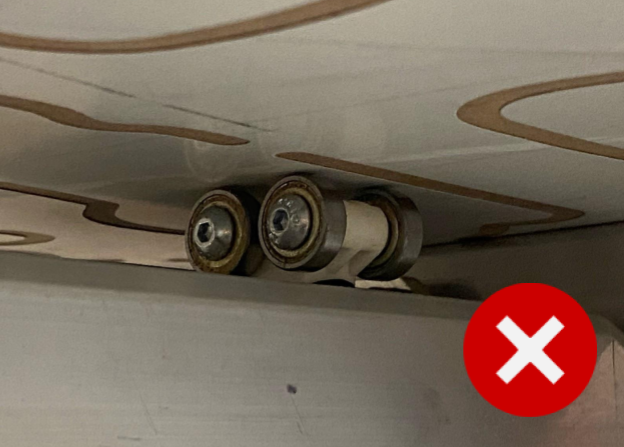
Use a smooth board
The spoil board MUST be new and smooth.

The lower roller wheels need to run along a flat surface to maintain accuracy.
When you don’t need a self-healing mat
If you’re drawing or only cutting thin materials which have a backing then you only need a rigid flat board as described earlier.
When you might need a self-healing mat
If you are cutting material:
without a backing, or
thicker material which may require locking out the travel of CNC stylus
you may want to consider purchasing a self healing mat, and bonding that to a board.
To find out more about cutting mats, please click this link: Large Self Healing Mats
Using tape
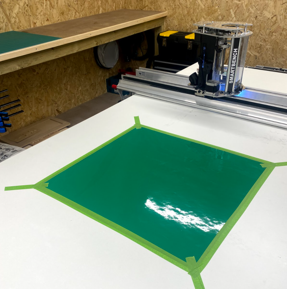
There are several different ways to hold material down to your spoil board. You should ensure your material is as flat as possible and that your material does not lift or move.
We would recommend using a low tack tape along all edges such as masking tape or Scotch Blue Tape.
Other methods
You can also explore other options, some may work better than others but this is depending on your material and application, one example being spray mount.

Paper resources
We like using background paper as it comes in large rolls. Click here for an example.
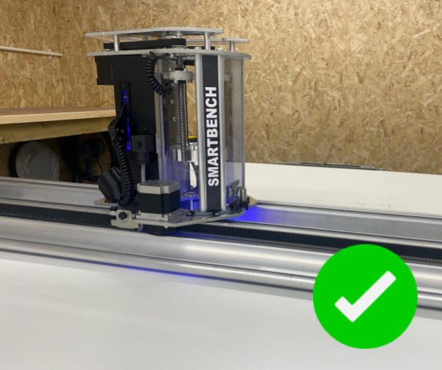
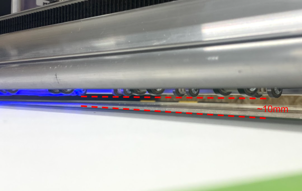
Clamp the upper X Beam above the material
To ensure the wheel units on the upper beam do not crease your drawing material, the upper beam will need to be raised to a fixed position around 10mm above your material.
How do I set the X beam height?
To set the X beam height, loosen the clamp on each end of the upper X beam.

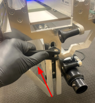
Lift the X beam up so that the wheels are around 10mm from the material ensuring it is parallel. You may want to use a piece of material to set this more consistently.
To secure the beam, retighten the clamp handles.
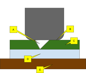
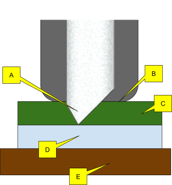
How the cartridge works
The blade (A) projects out of the cartridge nose (B). A pressure is applied to the cartridge nose (B) so that the cartridge nose is in contact with the top surface of the vinyl. This means blade will always cut a consistent depth relative to the top surface.
A: Blade
B: Cartridge nose
C: Vinyl
D: Vinyl backing
E: Base board
Setting the blade height
When cutting vinyl, setting the correct blade height is especially important. If you do not set the blade height correctly, you can end up cutting too far through your material, or not far enough. To set the blade height, follow the steps below.
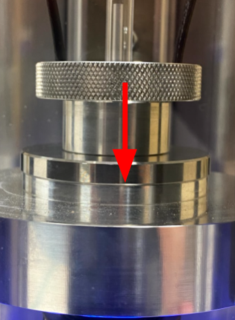
Insert the blade you wish to use into the vinyl cartridge
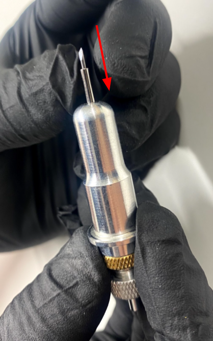
Loosen the gold locking ring on the vinyl cartridge

Rotate the top part of the cartridge assembly until the blade extends from the cartridge the correct amount
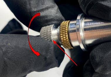
Tighten the gold locking ring to fix the blade height.

IMPORTANT: The blade should be set to extend from the cartridge system the same distance as the thickness of the material you wish to cut. |

For example, if you are cutting a self-adhesive vinyl then you will need to ensure the blade (A) is only cutting through the top layer i.e. the vinyl (C), and not the backing paper (D).
A: Blade
B: Cartridge nose
C: Vinyl
D: Vinyl backing
E: Base board
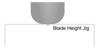
Inspection jig
We have included a blade height jig which will allow you to clearly see how far the blade extends from the cartridge.
To use the jig, hold the cartridge against the edge of the flat face. This will allow you to clearly see how far the blade extends from the cartridge and adjust, as necessary.

How to test
We would strongly recommend testing the blade height on a scrap piece of vinyl before committing to your project.
Once the blade height has been set, manually drag the cartridge over the scrap vinyl piece:

How to inspect the result
Here are some examples of good and bad results:
X: Blade has not cut deep enough. The vinyl has not been cut all the way through, just scratched.
Y: Blade has cut too deep. Both the vinyl and the backing paper have been cut.
Z: Blade at perfect height. Only the vinyl has been cut, the backing paper has not been cut. The vinyl can be peeled from the backing paper.

Final checks
Make sure that the golden lock ring is tight before loading into CNC Stylus. If it comes loose, then the blade height may change mid job! |

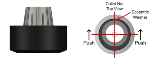
Fitting and removing a collet
You will need to select the 16-15mm collet size to hold the cartridge. Collet sizes can be found on the side of the collet for the larger collets.

The nut features an eccentric washer which requires force to be applied to a specific side to allow engagement and removal of the collet with the nut.
After selecting your collet, you will need to push it into the nut until it engages.
You will hear an audible click. You can check this by inverting the assembly. If the collet is fitted correctly, the collet will not fall out.

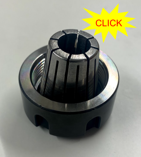
To remove the collet, push the collet to the side using your thumb. You may need to rotate the direction of force against the nut.
Loading the vinyl cutting cartridge
Once you have selected the correct size collet and have fitted the collet to the collet nut. You can now insert the vinyl cutting cartridge into the stylus. In the diagram below, you can see the part of the assembly we need to clamp onto to effectively hold the cartridge.

The cartridge should extend roughly 15mm from the CNC Stylus. Ensure the cartridge is parallel to the axis.

If the cartridge is not clamped parallel, this may cause the vinyl to tear during the cut. |

Fitting CNC Stylus to SmartBench
Using the loop, lower the CNC Stylus into the Z Head until the boss sits in the spindle collar.
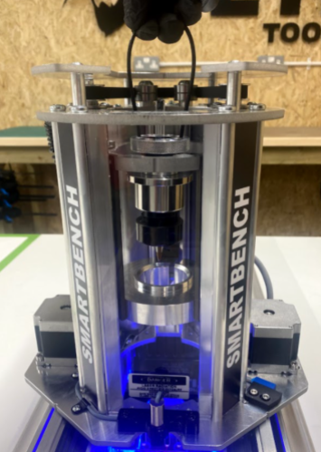
Check that the boss has fully inserted into the collar.
Using the 6mm hex driver, tighten the hex bolt. You should tighten the hex bolt until you feel resistance and then continue to tighten a QUARTER turn.
NOTE: No more than 5nm of torque is necessary.

What does this mean?
We have already set our XY datum in the job file when we made it previously in CAD. Now we need to set an XY datum in SmartBench. This gives SmartBench a reference point to work from.
For more theory about datums click here.
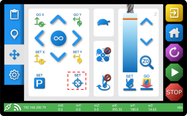
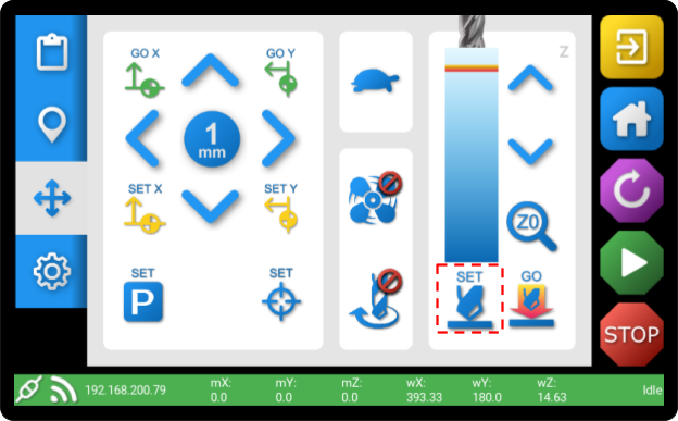
How do I set the SmartBench XY datum using the tool as a pointer?
To set a datum using the tool as your reference point, using the arrows to move the tool to your selected point.

You may need to lower the tool using the Z axis controls

Once you have moved your tool to the correct place, you can then press SET
For further details on how to set an XY datum on Smartbench, click here.
What is a Z datum?
We have already set our Z datum in the job file when we made it previously in CAD. Now we need to set a Z datum in SmartBench. This gives SmartBench a reference point to work from.
For more theory about datums click here.
A Z datum is typically set to the top, or the bottom of the material you are working with. For this tutorial, we are referencing the top. |

How do I set the Z datum with a pen in CNC Stylus?
After fitting CNC Stylus with a pen, and loading into SmartBench, now we need to tell SmartBench where the pen touches the paper. This is the Z datum.
Using the console, we will now lower the Z axis until the pen touches the top of your material surface.
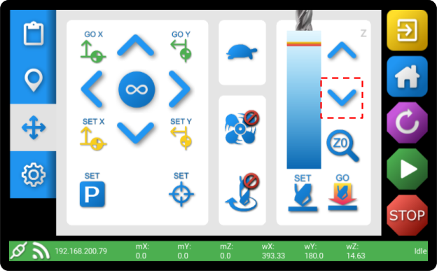
When the pen touches the material, we need to then continue to move the Z axis down by a further 2mm. This puts the pen in the centre of the CNC Stylus’ allowable travel, enabling it to absorb any variation in flatness.
To do this, change the move increment to 1mm…

… and press the ‘Z down’ arrow twice.

You can now press SET to save the datum.
For further details on how to set a Z datum on Smartbench, click here.
Further details
Click here for further details on how to start a job from within the PRO app.
When the job has finished, you will be shown the file completion screen.

You can then carefully remove your new creation and marvel at your genius. We recommend using a scalpel or weeding kit to extract the finished shapes.

Cutting too deep or too shallow
Setting the blade height is critical to getting a good result. And it can be tricky when dealing with such thin materials. Click here to learn good techniques on setting the blade height correctly.
Not having the cartridge parallel to the axis
Clamping the vinyl cutting cartridge parallel to the barrel of CNC stylus is essential. If it is at an angle it will alter the blade height, rub unevenly.
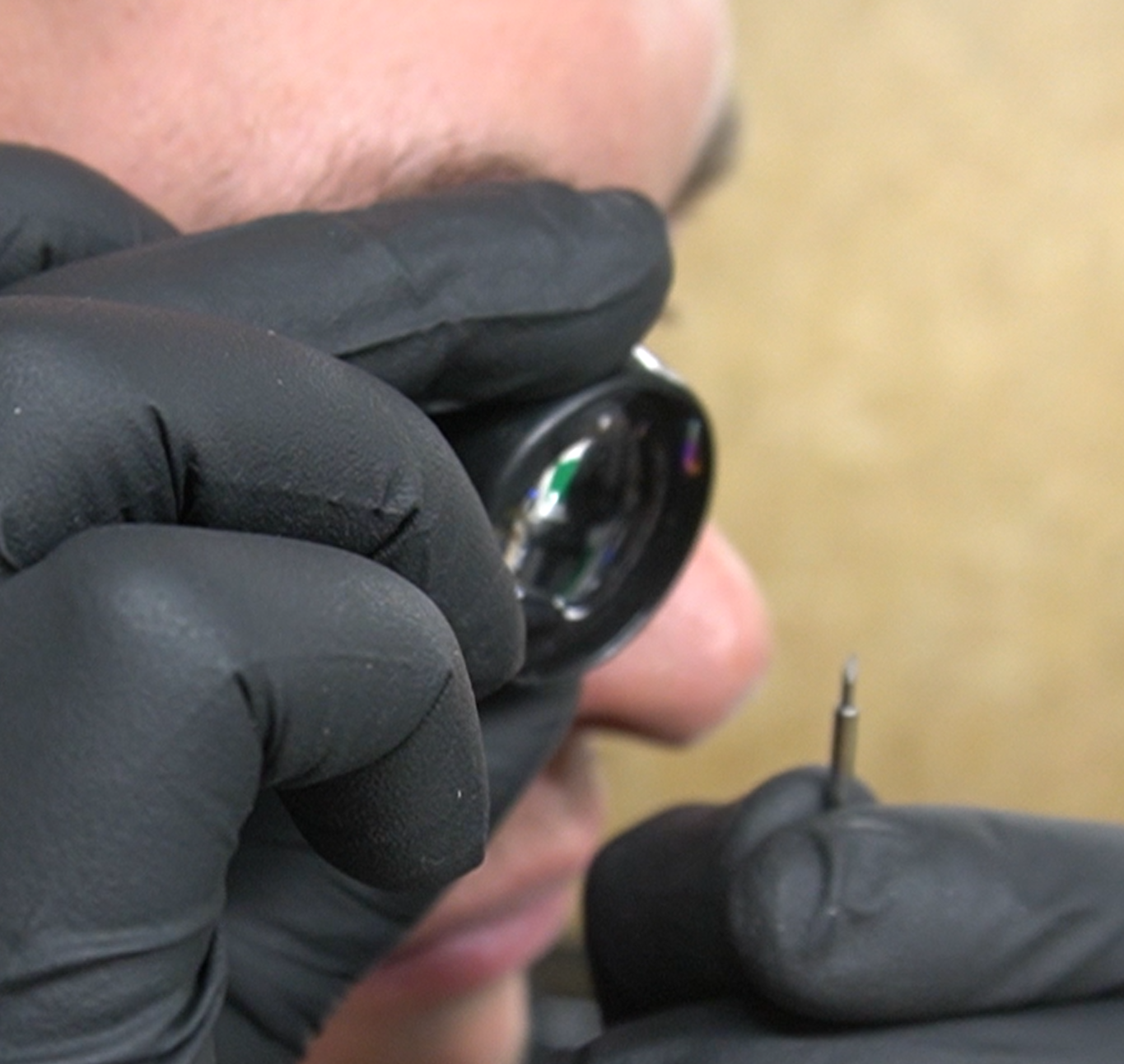
Using a blunt blade
Using a blunt blade will obviously give poor edge cutting results. We recommend using a magnification tool to get a good visual on the tip of the blade before cutting.
Using the wrong blade angle
Cutting with an unnecessarily steep blade can cause tearing. Check out our blade selection article to make sure you’re using the one that’s best for your material.
The vinyl not being completely flat and tight
Any looseness in the way the vinyl is held down will cause a “wave” of material in front of the cartridge. This can cause various different symptoms, so make sure your material is under tension when you tape it down.